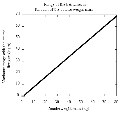
Figure 5
Mc=variable, Mp=0.5
Lc=0.5, Lp=0.8
Sa=-46
Figure 5 gives a real surprise when compared to the Figure 3. The constants had the following values: Mp=0.5, Lc=0.5, Lp=0.8 and Sa=-46. The counterweight varying does not have the same effect on the range as the projectile varying! Something very interesting can be derived from the graph because it is a straight line from the point where the trebuchet just throws the projectile onwards. If a certain trebuchet needs a counterweight of x kg to just throw a certain projectile and it needs a counterweight y kg heavier to throw the projectile 100 m, then to throw that same projectile 200m, the counterweight mass must x+2y kg and to throw the projectile n×100m the counterweight must have a mass of x+ny kg. This is a very useful when trying to hit a target because if you know the values of x and y for your trebuchet, you can easily calculate the counterweight needed to throw your projectile any given distance.

Figure 6
Mc=30, Mp=0.5
Lc=0.5, Lp=0.8
Sa=-46 or -11
Figure 6 shows the optimal firing angle of the trebuchet in function of the range of the trebuchet at this angle. This means the program calculated the best firing angle and range for each shot and a graph was drawn from this data. The constants have the following values: Mc=30, Mp=0.5, Lc=0.5, Lp=0.8 and Sa=-46 or -11. This graph allows us to see that the best angle is very rarely 45 degrees as we may assume. When the trebuchet can only just throw the projectile, a smaller angle is better. That means that the projectile should be thrown before the trebuchet reaches 45 degrees. The actual angle the projectile leaves at perpendicular to the projectile arm is larger that 45 degrees. This early throw can be explained because the trebuchet has the greatest angular acceleration at 0 degrees and afterwards the acceleration drops. If it becomes negative, the speed of the whole arm falls. If the projectile was shot at 45 degrees, the trebuchet would have slowed down so much that waiting for the right angle was 'not worth it'. When the speed is much greater it 'is worth it' to wait after 45 degrees, sacrificing the right angle for some more speed. The curves do however flatten out after a while so there would probably be a largest possible best angle for any given trebuchet. Note that if the starting angle is greater, the projectile and trebuchet has less time to accelerate and so a larger angle is better as the acceleration is 'needed more'.

Figure 7
Mc=30, Mp=0.5
Lc=0.5, Lp=0.8
Sa=-46 or -11
Figure 7 is similar to figure 6 and it gives the best firing angle in function of the angular velocity when the trebuchet arm is parallel to the ground. The constants have the same values as in figure 6. This figure is similar to figure 6 because the velocity at 0 degrees in conjunction with the starting angle decides upon the maximum range which was used to plot figure 6. On this graph the computer error described in part IV is most visible. The zigzag effect can clearly be seen on the curve with a starting angle of -46 degrees. The angles -46 and -11 degrees were chosen because the program worked in radians and -0.8 radians was the simplest angle close to -45 degrees, the probable starting angle for most trebuchets and -0.2 radians was larger and simple. It seemed like a good second angle to test ideas.
BackNextHome
© Filip Radlinski 1996, 1997